More Information about stainless steel shapes
We introduce the manufacturing items, chemical composition, mechanical properties, physical properties and surface finish of stainless steel.
Manufactured item
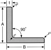
 Angle
Angle
Manufacturing dimensions and unit mass
| Edge A×B |
Thickness (t) | |||||||||
|---|---|---|---|---|---|---|---|---|---|---|
| 3 | 4 | 5 | 6 | 7 | 8 | 9 | 10 | 12 | 15 | |
| 20×20 | 0.894 | 1.16 | 1.38 | |||||||
| 25×25 | 1.13 | 1.46 | 1.78 | 2.07 | ||||||
| 30×30 | 1.37 | 1.77 | 2.18 | 2.54 | ||||||
| 40×40 | 1.85 | 2.41 | 2.98 | 3.50 | ||||||
| 50×50 | 2.37 | 3.09 | 3.81 | 4.48 | 5.17 | 5.84 | 6.44 | 7.12 | 8.36 | |
| 60×60 | 4.60 | 5.44 | 6.26 | 7.09 | 7.87 | 8.67 | ||||
| 65×65 | 5.05 | 5.97 | 6.87 | 7.74 | 8.64 | 9.52 | 11.2 | |||
| 75×75 | 5.82 | 6.92 | 7.98 | 9.01 | 10.1 | 11.1 | 13.1 | |||
| 80×80 | 7.40 | 8.53 | 9.64 | 10.8 | 11.9 | 14.1 | ||||
| 90×90 | 8.36 | 9.69 | 11.0 | 12.3 | 13.5 | 16.0 | ||||
| 100×100 | 9.32 | 10.8 | 12.2 | 13.7 | 15.1 | 17.9 | ||||
| 125×125 | 15.4 | 17.2 | 19.0 | 22.7 | 28.0 | |||||
| 150×150 | 20.9 | 23.1 | 27.5 | 33.8 | ||||||
- Standard manufacturing dimensions
- Shows optional dimensions
Remarks
Products of dimensions other than mentioned above can also be manufactured on request
Dimensional tolerance
| Edge A×B |
Leg tolerance | Thickness (t) and Thickness to lerance | |||||||||
|---|---|---|---|---|---|---|---|---|---|---|---|
| 3 | 4 | 5 | 6 | 7 | 8 | 9 | 10 | 12 | 15 | ||
| 20×20 | ≦1.5 | ±0.3 | ±0.3 | ±0.3 | ±0.3 | ||||||
| 25×25 | ≦1.5 | ±0.3 | ±0.3 | ±0.3 | ±0.3 | ||||||
| 30×30 | ≦2.0 | ±0.3 | ±0.3 | ±0.3 | ±0.3 | ||||||
| 40×40 | ≦2.0 | ±0.4 | ±0.4 | ±0.4 | ±0.4 | ||||||
| 50×50 | ≦2.0 | ±0.4 | ±0.4 | ±0.4 | ±0.4 | ±0.4 | ±0.4 | ±0.4 | ±0.4 | ±0.6 | |
| 60×60 | ≦3.0 | ±0.4 | ±0.4 | ±0.4 | ±0.4 | ±0.4 | ±0.4 | ||||
| 65×65 | ≦3.0 | ±0.4 | ±0.4 | ±0.4 | ±0.4 | ±0.4 | ±0.4 | ±0.6 | |||
| 75×75 | ≦3.0 | ±0.4 | ±0.4 | ±0.4 | ±0.4 | ±0.4 | ±0.4 | ±0.6 | |||
| 80×80 | ≦3.0 | ±0.4 | ±0.4 | ±0.4 | ±0.4 | ±0.4 | ±0.6 | ||||
| 90×90 | ≦3.0 | ±0.4 | ±0.4 | ±0.4 | ±0.4 | ±0.4 | ±0.6 | ||||
| 100×100 | ≦4.0 | ±0.4 | ±0.4 | ±0.4 | ±0.4 | ±0.4 | ±0.6 | ||||
| 125×125 | ≦4.0 | ±0.7 | ±0.7 | ±0.8 | ±0.8 | ±1.0 | |||||
| 150×150 | ≦4.0 | ±0.8 | ±1.0 | ±1.0 | ±1.0 | ||||||
- Standard manufacturing dimensions
- Shows optional dimensions
shape accuracy
| ltem | Tolerance |
|---|---|
| Squareness | 90°± 2° |
| Straightness | Less than 3 mm per 1 m Iess than [3 mm×overall length (m)/1 m] per overaii length |
| Length | (*1)4000, 6000, (max.7500) |
| Lengthtolerance | (*2) + 40 -0mm |
- *1For the sizes and lengths other than above please consult us
- *2The plus side of the length tolerance is a reference value
Shape accuracy
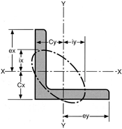
Geometrical moment of inertia:l = ai2
Radius of gyration of area : I = √l/a
Section modulus : Z = l/e
(a=cross-section area)
| Standard cross-sectional dimensions (mm) | Cross-section area (cm2) |
Center of gravity (cm) |
Geometrical moment of inertia (cm3) |
Radius of gyration of area (cm3) |
Section modulus (cm3) |
|||||||
|---|---|---|---|---|---|---|---|---|---|---|---|---|
| Edge A=B |
Thickness t |
r1 | r2 | a | Cx | Cy | lx | ly | ix | iy | Zx | Zy |
| 20 | 3 | 4 | 2 | 1.127 | 0.595 | 0.595 | 0.388 | 0.388 | 0.587 | 0.587 | 0.276 | 0.276 |
| 25 | 3 | 4 | 2 | 1.427 | 0.719 | 0.719 | 0.797 | 0.797 | 0.747 | 0.747 | 0.448 | 0.448 |
| 30 | 3 | 4 | 2 | 1.727 | 0.844 | 0.844 | 1.42 | 1.42 | 0.908 | 0.908 | 0.661 | 0.661 |
| 40 | 3 | 4.5 | 2 | 2.336 | 1.09 | 1.09 | 3.53 | 3.53 | 1.23 | 1.23 | 1.21 | 1.21 |
| 40 | 5 | 4.5 | 3 | 3.755 | 1.17 | 1.17 | 5.42 | 5.42 | 1.20 | 1.20 | 1.91 | 1.91 |
| 50 | 4 | 6.5 | 3 | 3.892 | 1.37 | 1.37 | 9.06 | 9.06 | 1.53 | 1.53 | 2.49 | 2.49 |
| 50 | 6 | 6.5 | 4.5 | 5.644 | 1.44 | 1.44 | 12.6 | 12.6 | 1.50 | 1.50 | 3.54 | 3.54 |
| 65 | 6 | 8.5 | 4 | 7.527 | 1.81 | 1.81 | 29.4 | 29.4 | 1.98 | 1.98 | 6.26 | 6.26 |
| 65 | 9 | 8.5 | 6 | 10.89 | 1.92 | 1.92 | 37.1 | 37.1 | 1.85 | 1.85 | 8.10 | 8.10 |
| 75 | 6 | 8.5 | 4 | 8.727 | 2.06 | 2.06 | 46.1 | 46.1 | 2.30 | 2.30 | 8.47 | 8.47 |
| 75 | 9 | 8.5 | 6 | 12.69 | 2.17 | 2.17 | 64.4 | 64.4 | 2.25 | 2.25 | 12.1 | 12.1 |
| 100 | 10 | 10 | 7 | 19.00 | 2.82 | 2.82 | 175 | 175 | 3.03 | 3.03 | 24.4 | 24.4 |
| 125 | 9 | 10 | 6 | 21.75 | 3.41 | 3.41 | 324 | 324 | 3.86 | 3.86 | 35.6 | 35.6 |
| 125 | 12 | 10 | 7 | 28.56 | 3.53 | 3.53 | 416 | 416 | 3.82 | 3.82 | 46.4 | 46.4 |
| 125 | 15 | 10 | 7 | 35.25 | 3.64 | 3.64 | 505 | 505 | 3.78 | 3.78 | 57.0 | 57.0 |
| 150 | 9 | 12 | 6 | 26.34 | 4.03 | 4.03 | 572 | 572 | 4.66 | 4.66 | 52.1 | 52.1 |
| 150 | 12 | 12 | 7 | 34.66 | 4.15 | 4.15 | 739 | 739 | 4.62 | 4.62 | 68.1 | 68.1 |
| 150 | 15 | 12 | 10 | 42.63 | 4.25 | 4.25 | 888 | 888 | 4.56 | 4.56 | 82.5 | 82.5 |
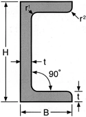
 Channel
Manufacturing dimensions and unit mass
| Flange X Web (B)× (H) |
Thickness (t) | ||||||||
|---|---|---|---|---|---|---|---|---|---|
| 4 | 5 | 6 | 7 | 8 | 9 | 10 | 12 | 15 | |
| 40×80 | 5.99 | ||||||||
| 50×100 | 6.20 | 7.65 | 9.02 | ||||||
| 65×130 | 12.0 | ||||||||
| 75×150 | 13.9 | 20.3 | |||||||
| 100×200 | 24.6 | 27.5 | 30.3 | 36.0 | |||||
- Welded Channel Bars
- Standard manufacturing dimensions
- Shows optional dimensions
Remarks
Available Size Range (Consut Us)
Dimensional tolerance
| Flange X Web (B)× (H) |
Edge Tolerance |
Width Tolerances of Webs |
Thickness (t) and Thicknesstolerance | ||||||||
|---|---|---|---|---|---|---|---|---|---|---|---|
| 4 | 5 | 6 | 7 | 8 | 9 | 10 | 12 | 15 | |||
| 40×80 | ±1.5 | ±1.5 | ±0.4 | ||||||||
| 50×100 | ±2.0 | ±2.0 | ±0.4 | ±0.4 | ±0.4 | ||||||
| 65×130 | ±2.0 | ±2.0 | ±0.5 | ||||||||
| 75×150 | ±2.0 | ±2.0 | ±0.5 | ±0.5 | |||||||
| 100×200 | ±3.0 | ±3.0 | ±0.5 | ±0.5 | ±0.6 | ±0.6 | |||||
- Welded Channel Bars
- Standard manufacturing dimensions
- Shows optional dimensions
Shape accuracy
| ltem | Tolerance |
|---|---|
| Squareness | 90°±2° |
| Straightness | Less than 3 mm per 1 m Iess than [3 mm×overall length (m)/1 m] per overaii length |
| Length | (*1)4000, 6000 |
| Lengthtolerance | (*2) + 40 -0mm |
- *1For the sizes and lengths other than above please consult us
- *2The plus side of the length tolerance is a reference value
Section modulus
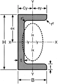
Geometrical moment of inertia : l = ai2
Radius of gyration of area : I = √l/a
Section modulus : Z = l/e
(a=cross-section area)
| Standard cross-sectional dimensions (mm) | Cross-section area (cm2) |
Center of gravity (cm) |
Geometrical moment of inertia (cm3) |
Radius of gyration of area (cm3) |
Section modulus (cm3) |
||||||
|---|---|---|---|---|---|---|---|---|---|---|---|
| Thickness×Flange×Web (t)× (B)× (H) |
r1 | r2 | a | Cx | Cy | lx | ly | ix | iy | Zx | Zy |
| 4×50×100 | 6.5 | 3 | 7.823 | 0 | 1.36 | 121 | 18.2 | 3.93 | 1.52 | 24.2 | 4.99 |
| 5×40×80 | 4.5 | 3 | 7.548 | 0 | 1.16 | 71.1 | 10.9 | 3.07 | 1.20 | 17.8 | 3.83 |
| 5×50×100 | 6.5 | 3 | 9.643 | 0 | 1.41 | 146 | 22.1 | 3.89 | 1.52 | 29.2 | 6.16 |
| 6×50×100 | 6.5 | 4.5 | 11.37 | 0 | 1.43 | 168 | 25.3 | 3.85 | 1.49 | 33.7 | 7.09 |
| 6×65×130 | 8.5 | 4 | 15.12 | 0 | 1.80 | 390 | 58.9 | 5.08 | 1.97 | 60.0 | 12.5 |
| 6×75×150 | 8.5 | 4 | 17.52 | 0 | 2.05 | 609 | 92.3 | 5.89 | 2.30 | 81.2 | 17.0 |
| 9×75×150 | 8.5 | 6 | 25.54 | 0 | 2.16 | 850 | 129 | 5.77 | 2.25 | 113 | 24.2 |
| 10×100×200 | 10 | 7 | 38.22 | 0 | 2.81 | 2310 | 351 | 7.77 | 3.03 | 231 | 48.8 |
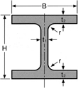
 Rolled H-Beam
Available Size Range and Properties
Rolled H-Beam
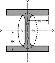
Geometrical moment of inertia : l = ai2
Radius of gyration of area : I = √l/a
Section modulus : Z = l/e
(a=cross-section area)
| Standard cross-sectional dimensions (mm) |
Cross-section area (cm2) |
Specific Gravity (kg/m) |
Geometrical moment of inertia (cm3) |
Radius of gyration of area (cm3) |
Section modulus (cm3) |
|||||||
|---|---|---|---|---|---|---|---|---|---|---|---|---|
| Dimensions (Web×Flange) |
(H)× (B) | t1 | t2 | r | a | SUS304 | lx | ly | ix | iy | Zx | Zy |
| 100×100 | 100×100 | 6 | 8 | 8 | 21.59 | 17.1 | 378 | 134 | 4.18 | 2.49 | 75.6 | 26.7 |
| 125×125 | 125×125 | 6.5 | 9 | 8 | 30.00 | 23.8 | 839 | 293 | 5.29 | 3.13 | 134 | 46.9 |
| 148×100 | 148×100 | 6 | 9 | 8 | 26.35 | 20.9 | 1000 | 150 | 6.17 | 2.39 | 135 | 30.1 |
| 150×150 | 150×150 | 7 | 10 | 8 | 39.65 | 31.4 | 1620 | 563 | 6.40 | 3.77 | 216 | 75.1 |
| 200×100 | 200×100 | 5.5 | 8 | 8 | 26.67 | 21.1 | 1810 | 134 | 8.23 | 2.24 | 181 | 26.7 |
| 200×200 | 200×200 | 8 | 12 | 13 | 63.53 | 50.4 | 4720 | 1600 | 8.62 | 5.02 | 472 | 160 |
| 250×250 | 250×250 | 9 | 14 | 13 | 91.43 | 72.5 | 10700 | 3650 | 10.8 | 6.32 | 860 | 292 |
Dimensional tolerance
| Item | Permited Variations of/in | Tolerance | |
|---|---|---|---|
| Edge (B) | ±3.0 | ||
| Web (H) | Nominal Diameter is less than 400mm. |
±3.0 | |
| Thickness | Flanges t2 |
Less Than 16 mm | ±1.0 |
| Webs t1 |
Less Than 16 mm | ±1.5 | |
| Length | 6000 | +40, -0 | |
| Item | Permited Variations of/in | Tolerance |
|---|---|---|
| Squareness | Nominal Diameter is less than or equal to 300mm. |
less than or equal to 1.2% of Width of Flange(B). However, the tolerance of minimum width is 2mm. |
| straightness | Nominal Diameter is less than or equal to 300mm. |
less than or equal to 0.2% of Width of Flange. |
| Deviation of the Center (s) | Nominal Diameter is less than or equal to 300mm. |
±3.0 |
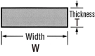
 Flat Bar
Standard manufacturing dimensions
- *Consult us for any other sizes.
| Thickness | Width | ||||||||||||||||
|---|---|---|---|---|---|---|---|---|---|---|---|---|---|---|---|---|---|
| 10 | 15 | 19 | 20 | 25 | 30 | 32 | 35 | 38 | 40 | 45 | 50 | 60 | 65 | 75 | 90 | 100 | |
| 3 | |||||||||||||||||
| 4 | |||||||||||||||||
| 5 | |||||||||||||||||
| 6 | |||||||||||||||||
- Standard manufacturing dimensions
- Products of dimensions other than mentioned above can also be manufactured on request
Dimensional tolerance
1. Thickness tolerance
| 3 ≦ ThicknessT ≦ 6 | Thickeness(T) is plus or minus 10% or less. |
|---|
2. Width Tolerances
(of Flanges)
| Width W < 25 | ±0.7 |
|---|---|
| 25 ≦ Width W ≦ 100 | ±1.0 |
Shape accuracy
| Straightness | ≦3mm/m, Total Length ≦3mm×Length(m)/m |
|---|---|
| Length tolerance | + 40mm, -0mm (Fixed length 4m) |
| Thickness | Width | |||
|---|---|---|---|---|
| 50 | 65 | 75 | 100 | |
| 9 | ||||
| 10 | ||||
| 11 | ||||
| 12 | ||||
| 13 | ||||
| 14 | ||||
| 15 | ||||
| 16 | ||||
- Standard manufacturing dimensions
Dimensional tolerance

1. Thickness tolerance
| Width W ≦ 50 | ±0.4 |
|---|---|
| 50 < Width W ≦ 100 | ±0.5 |
2. Width tolerance
| Width W ≦ 50 | ±0.8 |
|---|---|
| 50 < Width W ≦ 75 | ±1.2 |
| 75 < Width W ≦ 100 | ±1.5 |
Shape accuracy
| Straightness | ≦3mm/m, Total Length ≦3mm×Length(m)/m |
|---|---|
| Length tolerance | + 40mm, -0mm (Fixed length 4m) |
Suefase Finish
| Name | How to surfase finishing |
|---|---|
| Hot annealing and pickling | Materials which is heat treated and pickled after hot rolling |
 C shaped hot rolled bar
Manufacturing dimensions
| R1 (mm) | R2 (mm) | W1 (mm) | W2 (mm) | W3 (mm) | r1 (mm) | r2 (mm) | h1 (mm) | weight (kg:p) | L (m) |
|---|---|---|---|---|---|---|---|---|---|
| 25 | 13 | 50 | 45 | 23 | 16 | 3 | 7 | 38.5 | 5.5 (max. 7.0)* |
| 30 | 16 | 60 | 56 | 30 | 16 | 3 | 8 | 55.0 |
- *For the sizes and lengths other than above please consult us
Features
- C shaped hot rolled bars can be easily bent and welded compared with D shaped hot rolled bars.
- As the shape of the C shaped hot rolled bars are like ditch, the weight of them are lighter than that of D shaped which helps you save the cost.
Examples of use
- Reinforcement materials for marine
Chemical Composition
| NAR Standard [Corresponding JIS] |
Chemical Composition (mass%) |
|||||||
|---|---|---|---|---|---|---|---|---|
| C | Si | Mn | P | S | Cr | Ni | Mo | |
| NAR-304 (SUS304) |
≦0.08 | ≦1.00 | ≦2.00 | ≦0.040 | ≦0.030 | 18.00 - 20.00 | 8.00 - 10.50 | |
| NAR-304L (SUS304L) |
≦0.030 | ≦1.00 | ≦2.00 | ≦0.040 | ≦0.030 | 18.00 - 20.00 | 9.00 - 12.00 | |
| NAR-316 (SUS316) |
≦0.08 | ≦1.00 | ≦2.00 | ≦0.040 | ≦0.030 | 16.00 - 18.00 | 10.00 - 14.00 | 2.00 - 3.00 |
| NAR-316L (SUS316L) |
≦0.030 | ≦1.00 | ≦2.00 | ≦0.040 | ≦0.030 | 16.00 - 18.00 | 12.00 - 15.00 | 2.00 - 3.00 |
Mechanical Properties
| NAR Standard [Corresponding JIS] |
Mechanical Properties | ||||
|---|---|---|---|---|---|
| 0.2%-Proof Strength [MPa] |
Tensile Strength [MPa] |
Elongation [%] |
Hardness | ||
| HBW | HRBS | ||||
| NAR-304 (SUS304) |
≧205 | ≧540 | ≧45 | ≦187 | ≦90 |
| NAR-304L (SUS304L) |
≧195 | ≧490 | ≧50 | ≦187 | ≦90 |
| NAR-316 (SUS316) |
≧225 | ≧540 | ≧45 | ≦187 | ≦90 |
| NAR-316L (SUS316L) |
≧195 | ≧490 | ≧45 | ≦187 | ≦90 |
Physical Properties
| NAR Standard [Corresponding JIS] |
Physical Properties | ||||||
|---|---|---|---|---|---|---|---|
| Specific Heat [J/kg⋅K] |
Melting Point [℃] |
Thermal Conductivity [W/m⋅K] |
Coefficient of Thermal Expansion [×10-6/K] |
Specific Electric Resistance [µΩ⋅cm] |
Elastic modulus [105N/mm2] |
Specific gravity | |
| NAR-304 (SUS304) |
500 | 1399 - 1454 | 16.3 | 17.3 | 72 | 1.93 | 7.93 |
| NAR-304L (SUS304L) |
500 | 1399 - 1454 | 16.3 | 17.3 | 72 | 1.93 | 7.93 |
| NAR-316 (SUS316) |
500 | 1371 - 1399 | 16.3 | 16.0 | 74 | 1.93 | 7.98 |
| NAR-316L (SUS316L) |
500 | 1371 - 1399 | 16.3 | 16.0 | 74 | 1.93 | 7.98 |
Surface Finish
| Name | How to surface finishing |
|---|---|
| Hot annealing and pickling | Materials which is heat treated and pickled after hot rolling |
For further product information
Product Quotes, and inquiries without complete information required in inquiry form may not be responded to. Selection of inquiries for reply online is at the sole discretion of NIPPON STEEL. We appreciate your understanding.