
News
- Apr. 18, 2025 The civil engineering package has been updated with the addition of “Hat+H (Hat-type sheet pile for Deep excavation)” and “STEEL PIPE PILES with ribs x Sat-in Pile Foundation”.
- Apr. 02, 2025 Designing Metal TranTixxii to be Used in the Largest Quantity in the World on Taiwanese Temple Roof
- Mar. 10, 2025 Nippon Steel Obtained SuMPO EPD Certifications for Pipes and Tubes Used in Chemical Industry and for Boilers
- Dec. 12, 2024 Titanium with Aesthetic Appearance “TranTixxii” Service Life Warranty Launch —Launch of a maximum 150-year warranty through additional extensions—
- Oct. 31, 2024
Launch of the overseas version of ProStruct™, a solution brand for the construction industry
—Expanding the packaged series of steel materials and solution technology to overseas construction markets— - Oct. 30, 2024 Participation in the Japan Pavilion at ADIPEC, the Energy-Related Exhibition in the Middle East
- Oct. 07, 2024 Nippon Steel Obtained SuMPO EPD (Formerly EcoLeaf) Certificationsfor Its Hot Extruded Steel Shapes
- Jul. 10, 2024 Long-term OCTG supply contract with Aker BP renewed –Strengthens strategic partnership through stable supply of OCTG–
- Jul. 03, 2024 Long-term OCTG supply contract with Equinor renewed –Strengthens strategic partnership through stable supply of OCTG–
- Jun. 14, 2024 Acceptance of Orders for High-Alloy Seamless OCTG and Employment of Green Steel “NSCarbolex Neutral” Finalized for CCS to Be Used in Construction Project for Blue Ammonia Manufacturing Plant in the State of Qatar
- May. 15, 2024 Adoption of Coating Cycle Extension Steel “CORSPACE” for the First Time in Overseas ODA Bridge Construction
- Apr. 23, 2024 Participation in OTC, an Energy-Related Exhibition in the U.S.
- Mar. 22, 2024 Designing Titanium TranTixxii wins the European “iF DESIGN AWARD 2024” —The world's first non-ferrous metal material to receive the award—
- Sep. 28, 2023 The Adoption of “NSCarbolex Neutral” steel product for geothermal project in the Netherlands operated by 85 Degrees Renewables.
- Mar. 11, 2022 Nippon Steel's TranTixxii and NIPPON STEEL Stainless Steel Corporation's NSSC220M featured on the roof of an international conference center in Jiangsu, China
- April 22, 2021 Nippon Steel to Launch ZAM®-EX high corrosion resistant coated steel sheets for overseas markets
- Oct. 01, 2020 Our new product "FeLuceTM" (hairline-finished electroplated steel sheet) wins the Good Design Award 2020 ~Our first steel sheet to win the Good Design Award~
- Feb. 14, 2019 NSSMC Receives Shell’s Supplier Award
- Jul. 30, 2018 Execution of Strategic Partnership with BP Oman
- Jul. 30, 2018 "The beauty of distinctive gradations make people feel nature" was posted.
- Jul. 26, 2018 VAM® 21 HT CLEANWELL® DRY ST First Running
- Jul. 19, 2018 Steel Wires Joint Venture Company for Cold Heading and Forging in USA (NSCI) holds an Opening Ceremony
- Jun. 27, 2018 NSSMC and Standard Steel Receive TTX “Excellent Supplier 2017” Award
- May. 29, 2018 NSSMC Named a Top 100 Global Innovator in 2017 for Sixth Consecutive Year
- Apr. 25, 2018 Steel Wires Joint Venture Company for Cold Heading and Forging in USA (NSCI) Starts Commercial Production
- Apr. 17, 2018 Strengthening Supply System for Ultra-high-tensile Steel Sheets New CGL to be installed at Kimitsu Works
- Feb. 27, 2018 Nippon Steel & Sumikin Crankshaft, NSSMC’s manufacturing and sales subsidiary of crankshafts in the U.S., earns Diamond Supplier Award from Navistar
- Aug. 04, 2017 NSSMC’s proprietary titanium product TranTixxii™ is adopted for cladding of a theater in Jiangsu Province, China
Stainless steel Shapes
We introduce the manufacturing items, chemical composition, mechanical properties, physical properties and surface finish of stainless steel.
Manufactured item
Angle
We can supply L type angles made of stainless steel. From whose size variety ranges 20 mm to 150 mm in width, which can be used for a wide range of applications.
Manufacturing dimensions and unit mass
| Edge A×B |
Thickness (t) | |||||||||
|---|---|---|---|---|---|---|---|---|---|---|
| 3 | 4 | 5 | 6 | 7 | 8 | 9 | 10 | 12 | 15 | |
| 20×20 | 0.894 | 1.16 | 1.38 | |||||||
| 25×25 | 1.13 | 1.46 | 1.78 | 2.07 | ||||||
| 30×30 | 1.37 | 1.77 | 2.18 | 2.54 | ||||||
| 40×40 | 1.85 | 2.41 | 2.98 | 3.50 | ||||||
| 50×50 | 2.37 | 3.09 | 3.81 | 4.48 | 5.17 | 5.84 | 6.44 | 7.12 | 8.36 | |
| 60×60 | 4.60 | 5.44 | 6.26 | 7.09 | 7.87 | 8.67 | ||||
| 65×65 | 5.05 | 5.97 | 6.87 | 7.74 | 8.64 | 9.52 | 11.2 | |||
| 75×75 | 5.82 | 6.92 | 7.98 | 9.01 | 10.1 | 11.1 | 13.1 | |||
| 80×80 | 7.40 | 8.53 | 9.64 | 10.8 | 11.9 | 14.1 | ||||
| 90×90 | 8.36 | 9.69 | 11.0 | 12.3 | 13.5 | 16.0 | ||||
| 100×100 | 9.32 | 10.8 | 12.2 | 13.7 | 15.1 | 17.9 | ||||
| 125×125 | 15.4 | 17.2 | 19.0 | 22.7 | 28.0 | |||||
| 150×150 | 20.9 | 23.1 | 27.5 | 33.8 | ||||||
 Standard manufacturing dimensions
 shows optional dimensions
Remarks
Products of dimensions other than mentioned above can also be manufactured on request
Dimensional tolerance
| Edge A×B |
Leg tolerance | Thickness (t) and Thickness to lerance | |||||||||
|---|---|---|---|---|---|---|---|---|---|---|---|
| 3 | 4 | 5 | 6 | 7 | 8 | 9 | 10 | 12 | 15 | ||
| 20×20 | ≦1.5 | ±0.3 | ±0.3 | ±0.3 | ±0.3 | ||||||
| 25×25 | ≦1.5 | ±0.3 | ±0.3 | ±0.3 | ±0.3 | ||||||
| 30×30 | ≦2.0 | ±0.3 | ±0.3 | ±0.3 | ±0.3 | ||||||
| 40×40 | ≦2.0 | ±0.4 | ±0.4 | ±0.4 | ±0.4 | ||||||
| 50×50 | ≦2.0 | ±0.4 | ±0.4 | ±0.4 | ±0.4 | ±0.4 | ±0.4 | ±0.4 | ±0.4 | ±0.6 | |
| 60×60 | ≦3.0 | ±0.4 | ±0.4 | ±0.4 | ±0.4 | ±0.4 | ±0.4 | ||||
| 65×65 | ≦3.0 | ±0.4 | ±0.4 | ±0.4 | ±0.4 | ±0.4 | ±0.4 | ±0.6 | |||
| 75×75 | ≦3.0 | ±0.4 | ±0.4 | ±0.4 | ±0.4 | ±0.4 | ±0.4 | ±0.6 | |||
| 80×80 | ≦3.0 | ±0.4 | ±0.4 | ±0.4 | ±0.4 | ±0.4 | ±0.6 | ||||
| 90×90 | ≦3.0 | ±0.4 | ±0.4 | ±0.4 | ±0.4 | ±0.4 | ±0.6 | ||||
| 100×100 | ≦4.0 | ±0.4 | ±0.4 | ±0.4 | ±0.4 | ±0.4 | ±0.6 | ||||
| 125×125 | ≦4.0 | ±0.7 | ±0.7 | ±0.8 | ±0.8 | ±1.0 | |||||
| 150×150 | ≦4.0 | ±0.8 | ±1.0 | ±1.0 | ±1.0 | ||||||
 Standard manufacturing dimensions
 Shows optional dimensions
shape accuracy
| ltem | Tolerance |
|---|---|
| Squareness | 90°± 2° |
| Straightness | Less than 3 mm per 1 m Iess than [3 mm×overall length (m)/1 m] per overaii length |
| Length | (*1)4000, 6000, (max.7500) |
| Lengthtolerance | (*2) + 40 -0mm |
*1 For the sizes and lengths other than above please consult us
*2 The plus side of the length tolerance is a reference value
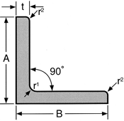
Shape accuracy
Geometrical moment of inertia:l = ai2
Radius of gyration of area : I = √l/a
Section modulus : Z = l/e
(a=cross-section area)
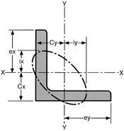
| Standard cross-sectional dimensions (mm) | Cross-section area (cm2) |
Center of gravity (cm) |
Geometrical moment of inertia (cm3) |
Radius of gyration of area (cm3) |
Section modulus (cm3) |
|||||||
|---|---|---|---|---|---|---|---|---|---|---|---|---|
| Edge A=B |
Thickness t |
r1 | r2 | a | Cx | Cy | lx | ly | ix | iy | Zx | Zy |
| 20 | 3 | 4 | 2 | 1.127 | 0.595 | 0.595 | 0.388 | 0.388 | 0.587 | 0.587 | 0.276 | 0.276 |
| 25 | 3 | 4 | 2 | 1.427 | 0.719 | 0.719 | 0.797 | 0.797 | 0.747 | 0.747 | 0.448 | 0.448 |
| 30 | 3 | 4 | 2 | 1.727 | 0.844 | 0.844 | 1.42 | 1.42 | 0.908 | 0.908 | 0.661 | 0.661 |
| 40 | 3 | 4.5 | 2 | 2.336 | 1.09 | 1.09 | 3.53 | 3.53 | 1.23 | 1.23 | 1.21 | 1.21 |
| 40 | 5 | 4.5 | 3 | 3.755 | 1.17 | 1.17 | 5.42 | 5.42 | 1.20 | 1.20 | 1.91 | 1.91 |
| 50 | 4 | 6.5 | 3 | 3.892 | 1.37 | 1.37 | 9.06 | 9.06 | 1.53 | 1.53 | 2.49 | 2.49 |
| 50 | 6 | 6.5 | 4.5 | 5.644 | 1.44 | 1.44 | 12.6 | 12.6 | 1.50 | 1.50 | 3.54 | 3.54 |
| 65 | 6 | 8.5 | 4 | 7.527 | 1.81 | 1.81 | 29.4 | 29.4 | 1.98 | 1.98 | 6.26 | 6.26 |
| 65 | 9 | 8.5 | 6 | 10.89 | 1.92 | 1.92 | 37.1 | 37.1 | 1.85 | 1.85 | 8.10 | 8.10 |
| 75 | 6 | 8.5 | 4 | 8.727 | 2.06 | 2.06 | 46.1 | 46.1 | 2.30 | 2.30 | 8.47 | 8.47 |
| 75 | 9 | 8.5 | 6 | 12.69 | 2.17 | 2.17 | 64.4 | 64.4 | 2.25 | 2.25 | 12.1 | 12.1 |
| 100 | 10 | 10 | 7 | 19.00 | 2.82 | 2.82 | 175 | 175 | 3.03 | 3.03 | 24.4 | 24.4 |
| 125 | 9 | 10 | 6 | 21.75 | 3.41 | 3.41 | 324 | 324 | 3.86 | 3.86 | 35.6 | 35.6 |
| 125 | 12 | 10 | 7 | 28.56 | 3.53 | 3.53 | 416 | 416 | 3.82 | 3.82 | 46.4 | 46.4 |
| 125 | 15 | 10 | 7 | 35.25 | 3.64 | 3.64 | 505 | 505 | 3.78 | 3.78 | 57.0 | 57.0 |
| 150 | 9 | 12 | 6 | 26.34 | 4.03 | 4.03 | 572 | 572 | 4.66 | 4.66 | 52.1 | 52.1 |
| 150 | 12 | 12 | 7 | 34.66 | 4.15 | 4.15 | 739 | 739 | 4.62 | 4.62 | 68.1 | 68.1 |
| 150 | 15 | 12 | 10 | 42.63 | 4.25 | 4.25 | 888 | 888 | 4.56 | 4.56 | 82.5 | 82.5 |
Channel
Stainless Steel Channel Bars / From w-40mm(Lower Limit) to w-100mm(Upper Limit) sizes are available.
Manufacturing dimensions and unit mass
| Flange X Web (B)× (H) |
Thickness (t) | ||||||||
|---|---|---|---|---|---|---|---|---|---|
| 4 | 5 | 6 | 7 | 8 | 9 | 10 | 12 | 15 | |
| 40×80 | 5.99 | ||||||||
| 50×100 | 6.20 | 7.65 | 9.02 | ||||||
| 65×130 | 12.0 | ||||||||
| 75×150 | 13.9 | 20.3 | |||||||
| 100×200 | 24.6 | 27.5 | 30.3 | 36.0 | |||||
 Welded Channel Bars
 Standard manufacturing dimensions
 Shows optional dimensions
Remarks
Available Size Range (Consut Us)
Dimensional tolerance
| Flange X Web (B)× (H) |
Edge Tolerance |
Width Tolerances of Webs |
Thickness (t) and Thicknesstolerance | ||||||||
|---|---|---|---|---|---|---|---|---|---|---|---|
| 4 | 5 | 6 | 7 | 8 | 9 | 10 | 12 | 15 | |||
| 40×80 | ±1.5 | ±1.5 | ±0.4 | ||||||||
| 50×100 | ±2.0 | ±2.0 | ±0.4 | ±0.4 | ±0.4 | ||||||
| 65×130 | ±2.0 | ±2.0 | ±0.5 | ||||||||
| 75×150 | ±2.0 | ±2.0 | ±0.5 | ±0.5 | |||||||
| 100×200 | ±3.0 | ±3.0 | ±0.5 | ±0.5 | ±0.6 | ±0.6 | |||||
 Welded Channel Bars
 Standard manufacturing dimensions
 Shows optional dimensions
Shape accuracy
| ltem | Tolerance |
|---|---|
| Squareness | 90°±2° |
| Straightness | Less than 3 mm per 1 m Iess than [3 mm×overall length (m)/1 m] per overaii length |
| Length | (*1)4000, 6000 |
| Lengthtolerance | (*2) + 40 -0mm |
*1 For the sizes and lengths other than above please consult us
*2 The plus side of the length tolerance is a reference value
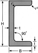
Section modulus
Geometrical moment of inertia : l = ai2
Radius of gyration of area : I = √l/a
Section modulus : Z = l/e
(a=cross-section area)
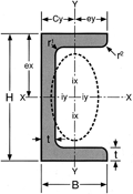
| Standard cross-sectional dimensions (mm) | Cross-section area (cm2) |
Center of gravity (cm) |
Geometrical moment of inertia (cm3) |
Radius of gyration of area (cm3) |
Section modulus (cm3) |
||||||
|---|---|---|---|---|---|---|---|---|---|---|---|
| Thickness×Flange×Web (t)× (B)× (H) |
r1 | r2 | a | Cx | Cy | lx | ly | ix | iy | Zx | Zy |
| 4×50×100 | 6.5 | 3 | 7.823 | 0 | 1.36 | 121 | 18.2 | 3.93 | 1.52 | 24.2 | 4.99 |
| 5×40×80 | 4.5 | 3 | 7.548 | 0 | 1.16 | 71.1 | 10.9 | 3.07 | 1.20 | 17.8 | 3.83 |
| 5×50×100 | 6.5 | 3 | 9.643 | 0 | 1.41 | 146 | 22.1 | 3.89 | 1.52 | 29.2 | 6.16 |
| 6×50×100 | 6.5 | 4.5 | 11.37 | 0 | 1.43 | 168 | 25.3 | 3.85 | 1.49 | 33.7 | 7.09 |
| 6×65×130 | 8.5 | 4 | 15.12 | 0 | 1.80 | 390 | 58.9 | 5.08 | 1.97 | 60.0 | 12.5 |
| 6×75×150 | 8.5 | 4 | 17.52 | 0 | 2.05 | 609 | 92.3 | 5.89 | 2.30 | 81.2 | 17.0 |
| 9×75×150 | 8.5 | 6 | 25.54 | 0 | 2.16 | 850 | 129 | 5.77 | 2.25 | 113 | 24.2 |
| 10×100×200 | 10 | 7 | 38.22 | 0 | 2.81 | 2310 | 351 | 7.77 | 3.03 | 231 | 48.8 |
Rolled H-Beam
Stainless Steel Rolled H-Beam
Available Size Range and Properties
Rolled H-Beam
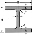
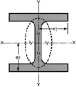
Geometrical moment of inertia : l = ai2
Radius of gyration of area : I = √l/a
Section modulus : Z = l/e
(a=cross-section area)
| Standard cross-sectional dimensions (mm) |
Cross-section area (cm2) |
Specific Gravity (kg/m) |
Geometrical moment of inertia (cm3) |
Radius of gyration of area (cm3) |
Section modulus (cm3) |
|||||||
|---|---|---|---|---|---|---|---|---|---|---|---|---|
| Dimensions (Web×Flange) |
(H)× (B) | t1 | t2 | r | a | SUS304 | lx | ly | ix | iy | Zx | Zy |
| 100×100 | 100×100 | 6 | 8 | 8 | 21.59 | 17.1 | 378 | 134 | 4.18 | 2.49 | 75.6 | 26.7 |
| 125×125 | 125×125 | 6.5 | 9 | 8 | 30.00 | 23.8 | 839 | 293 | 5.29 | 3.13 | 134 | 46.9 |
| 148×100 | 148×100 | 6 | 9 | 8 | 26.35 | 20.9 | 1000 | 150 | 6.17 | 2.39 | 135 | 30.1 |
| 150×150 | 150×150 | 7 | 10 | 8 | 39.65 | 31.4 | 1620 | 563 | 6.40 | 3.77 | 216 | 75.1 |
| 200×100 | 200×100 | 5.5 | 8 | 8 | 26.67 | 21.1 | 1810 | 134 | 8.23 | 2.24 | 181 | 26.7 |
| 200×200 | 200×200 | 8 | 12 | 13 | 63.53 | 50.4 | 4720 | 1600 | 8.62 | 5.02 | 472 | 160 |
| 250×250 | 250×250 | 9 | 14 | 13 | 91.43 | 72.5 | 10700 | 3650 | 10.8 | 6.32 | 860 | 292 |
Dimensional tolerance
| Item | Permited Variations of/in | Tolerance | |
|---|---|---|---|
| Edge (B) | ±3.0 | ||
| Web (H) | Nominal Diameter is less than 400mm. |
±3.0 | |
| Thickness |
Flanges |
Less Than 16 mm | ±1.0 |
| Webs t1 |
Less Than 16 mm | ±1.5 | |
| Length | 6000 | +40, -0 | |
| Item | Permited Variations of/in | Tolerance |
|---|---|---|
| Squareness | Nominal Diameter is less than or equal to 300mm. |
less than or equal to 1.2% of Width of Flange(B). However, the tolerance of minimum width is 2mm. |
| straightness | Nominal Diameter is less than or equal to 300mm. |
less than or equal to 0.2% of Width of Flange. |
| Deviation of the Center (s) | Nominal Diameter is less than or equal to 300mm. |
±3.0 |
Flat Bar
Stainless Steel Flat Bars / available for various usages
Standard manufacturing dimensions
* Consult us for any other sizes.
| Thickness | Width | ||||||||||||||||
|---|---|---|---|---|---|---|---|---|---|---|---|---|---|---|---|---|---|
| 10 | 15 | 19 | 20 | 25 | 30 | 32 | 35 | 38 | 40 | 45 | 50 | 60 | 65 | 75 | 90 | 100 | |
| 3 | |||||||||||||||||
| 4 | |||||||||||||||||
| 5 | |||||||||||||||||
| 6 | |||||||||||||||||
 Products of dimensions other than mentioned above can also be manufactured on request
 Standard manufacturing dimensions
Dimensional tolerance

1. Thickness tolerance
| 3 ≦ ThicknessT ≦ 6 | Thickeness(T) is plus or minus 10% or less. |
|---|
2. Width Tolerances
(of Flanges)
| Width W < 25 | ±0.7 |
|---|---|
| 25 ≦ Width W ≦ 100 | ±1.0 |
Shape accuracy
| Straightness | ≦3mm/m, Total Length ≦3mm×Length (m)/m |
|---|---|
| Length tolerance | + 40mm, -0mm (Fixed length 4m) |
| Thickness | Width | |||
|---|---|---|---|---|
| 50 | 65 | 75 | 100 | |
| 9 | ||||
| 10 | ||||
| 11 | ||||
| 12 | ||||
| 13 | ||||
| 14 | ||||
| 15 | ||||
| 16 | ||||
 Standard manufacturing dimensions
Dimensional tolerance

1. Thicknessのtolerance
| Width W ≦ 50 | ±0.4 |
|---|---|
| 50 < Width W ≦ 100 | ±0.5 |
2. Width tolerance
| Width W ≦ 50 | ±0.8 |
|---|---|
| 50 < Width W ≦ 75 | ±1.2 |
| 75 < Width W ≦ 100 | ±1.5 |
Shape accuracy
| Straightness | ≦3mm/m, Total Length ≦3mm×Length(m)/m |
|---|---|
| Length tolerance | + 40mm、-0mm (Fixed length 4m) |
Suefase Finish
| Name | How to surfase finishing |
|---|---|
| Hot annealing and pickling | Materials which is heat treated and pickled after hot rolling |
C shaped hot rolled bar
We supply Special C shaped hot rolled bars with supreme technology.
Manufacturing dimensions
| R1 (mm) | R2 (mm) | W1 (mm) | W2 (mm) | W3 (mm) | r1 (mm) | r2 (mm) | h1 (mm) | weight (kg:p) | L (m) |
|---|---|---|---|---|---|---|---|---|---|
| 25 | 13 | 50 | 45 | 23 | 16 | 3 | 7 | 38.5 | 5.5 (max. 7.0)* |
| 30 | 16 | 60 | 56 | 30 | 16 | 3 | 8 | 55.0 |
* For the sizes and lengths other than above please consult us
Features
- C shaped hot rolled bars can be easily bent and welded compared with D shaped hot rolled bars.
- As the shape of the C shaped hot rolled bars are like ditch, the weight of them are lighter than that of D shaped which helps you save the cost.
Examples of use
- Reinforcement materials for marine
Chemical Composition
| NAR Standard [Corresponding JIS] |
Chemical Composition (mass%) |
|||||||
|---|---|---|---|---|---|---|---|---|
| C | Si | Mn | P | S | Cr | Ni | Mo | |
| NAR-304 (SUS304) |
≦0.08 | ≦1.00 | ≦2.00 | ≦0.040 | ≦0.030 | 18.00 - 20.00 | 8.00 - 10.50 | |
| NAR-304L (SUS304L) |
≦0.030 | ≦1.00 | ≦2.00 | ≦0.040 | ≦0.030 | 18.00 - 20.00 | 9.00 - 12.00 | |
| NAR-316 (SUS316) |
≦0.08 | ≦1.00 | ≦2.00 | ≦0.040 | ≦0.030 | 16.00 - 18.00 | 10.00 - 14.00 | 2.00 - 3.00 |
| NAR-316L (SUS316L) |
≦0.030 | ≦1.00 | ≦2.00 | ≦0.040 | ≦0.030 | 16.00 - 18.00 | 12.00 - 15.00 | 2.00 - 3.00 |
Mechanical Properties
| NAR Standard [Corresponding JIS] |
Mechanical Properties | ||||
|---|---|---|---|---|---|
| 0.2%-Proof Strength [MPa] |
Tensile Strength [MPa] |
Elongation [%] |
Hardness | ||
| HBW | HRBS | ||||
| NAR-304 (SUS304) |
≧205 | ≧540 | ≧45 | ≦187 | ≦90 |
| NAR-304L (SUS304L) |
≧195 | ≧490 | ≧50 | ≦187 | ≦90 |
| NAR-316 (SUS316) |
≧225 | ≧540 | ≧45 | ≦187 | ≦90 |
| NAR-316L (SUS316L) |
≧195 | ≧490 | ≧45 | ≦187 | ≦90 |
Physical Properties
| NAR Standard [Corresponding JIS] |
Physical Properties | ||||||
|---|---|---|---|---|---|---|---|
| Specific Heat [J/kg⋅K] |
Melting Point [℃] |
Thermal Conductivity [W/m⋅K] |
Coefficient of Thermal Expansion [×10-6/K] |
Specific Electric Resistance [µΩ⋅cm] |
Elastic modulus [105N/mm2] |
Specific gravity | |
| NAR-304 (SUS304) |
500 | 1399 - 1454 | 16.3 | 17.3 | 72 | 1.93 | 7.93 |
| NAR-304L (SUS304L) |
500 | 1399 - 1454 | 16.3 | 17.3 | 72 | 1.93 | 7.93 |
| NAR-316 (SUS316) |
500 | 1371 - 1399 | 16.3 | 16.0 | 74 | 1.93 | 7.98 |
| NAR-316L (SUS316L) |
500 | 1371 - 1399 | 16.3 | 16.0 | 74 | 1.93 | 7.98 |
Surface Finish
| Name | How to surface finishing |
|---|---|
| Hot annealing and pickling | Materials which is heat treated and pickled after hot rolling |
Contact Information
For further product information
Product Quotes, and inquiries without complete information required in inquiry form may not be responded to. Selection of inquiries for reply online is at the sole discretion of NIPPON STEEL. We appreciate your understanding.
